DC Power Analyzer
Complete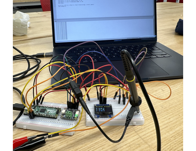
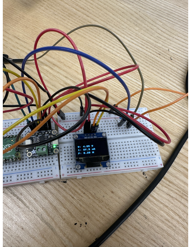
I designed the DC Power Analyzer as a precise tool for measuring the voltage, current, and power use of DC devices. It displays exactly how much power a circuit is using.
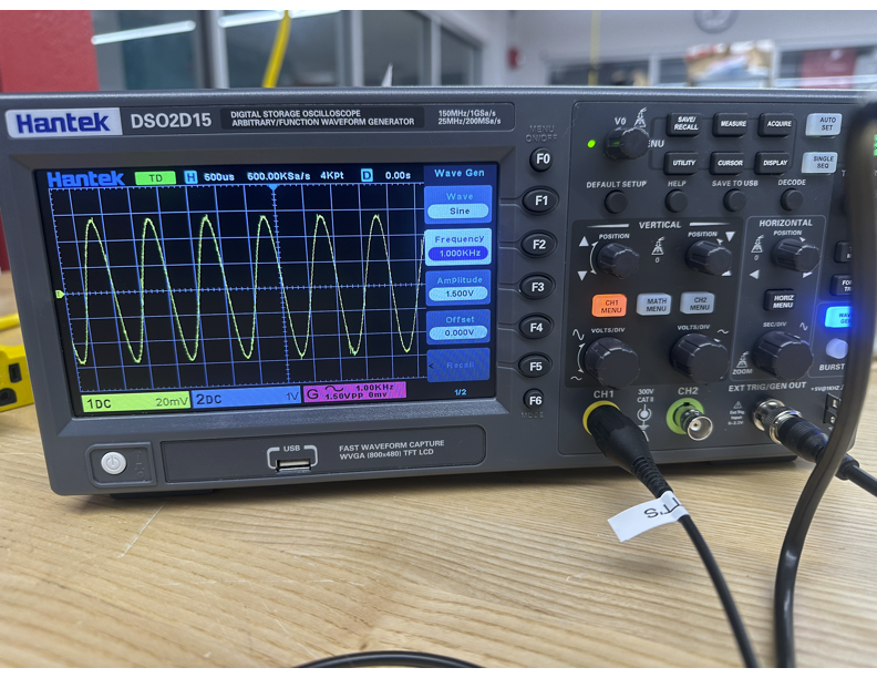
The main part of the analyzer is a custom current-sense amplifier using the INA180, which sends its signal through a Sallen-Key anti-aliasing filter before digitization. I simulated the whole signal chain in LTspice to verify the amplifier and filter, then tested the real hardware on the oscilloscope to confirm it matched my predictions. The working breadboard prototype reads voltage, current, and power live on an OLED display, validated within 1% of a calibrated multimeter.
In Altium Designer, my PCB design focused on the analog details that affect measurement accuracy, including careful ground-plane management, Kelvin (4-wire) sensing for precise current readings, and keeping the analog and digital sections separate to avoid noise in the measurements.
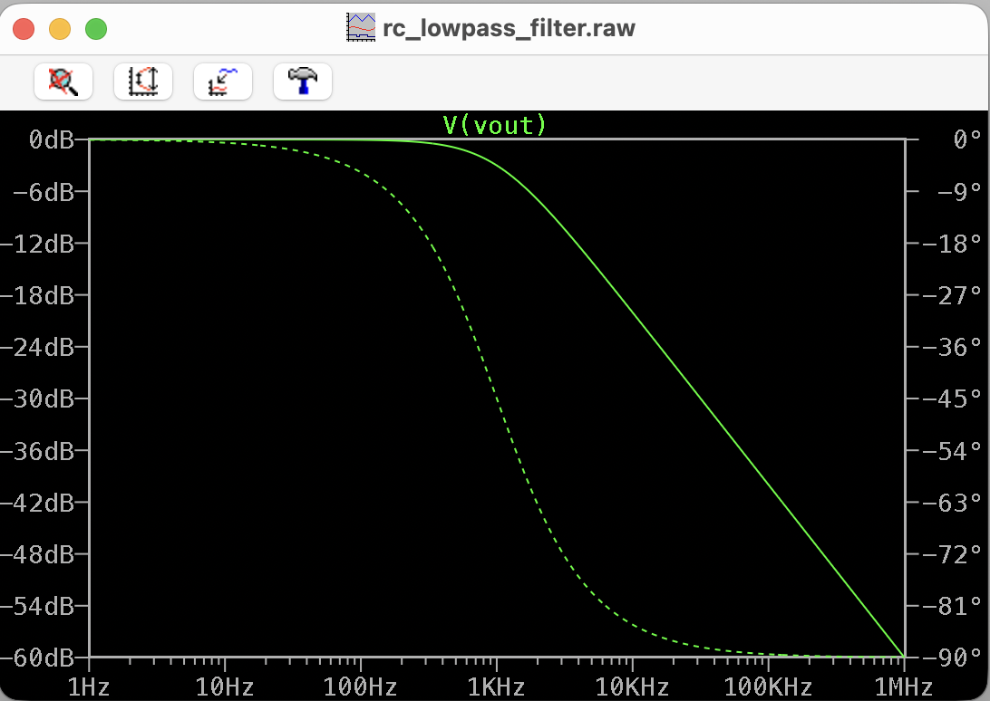
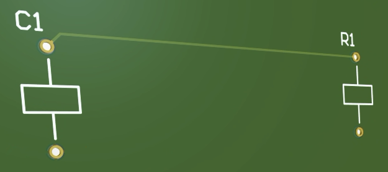
To reduce risk with the custom board, I started by taking a simple RC low-pass filter (the same 1.5k ohm and 100nF filter I tested on a breadboard with a cutoff near 1kHz) through the full PCB process in Altium Designer. I went from schematic capture to component footprints, board layout, 3D review, and finally generated the Gerber and NC drill files. This let me test the whole design-to-fabrication process before moving on to the full analyzer.
I started this project because I wanted to build something truly focused on electrical engineering and analog design. I was looking for a real signal-chain challenge, not just another beginner microcontroller project. I completed it as a working prototype and carried the analog design and PCB skills straight into my current project, the FOC motor controller and reaction-wheel inverted pendulum.