FOC Motor Controller and Reaction-Wheel Inverted Pendulum
In Progress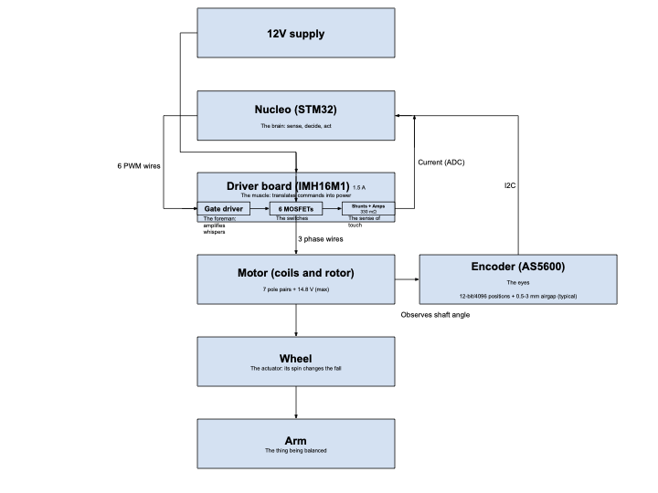
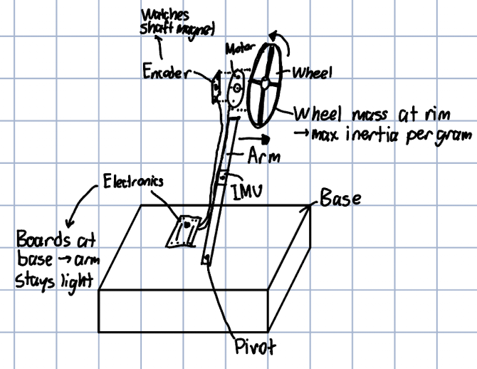
I am building my own field-oriented control (FOC) brushless motor controller for a reaction-wheel inverted pendulum. The robot will stay balanced by spinning a flywheel to create torque. My goal is to design and build every part myself, including the power electronics, PCB, control firmware, and mechanical parts.
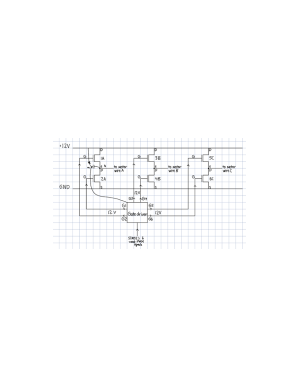
I took on this project by myself to learn more about actuation and closed-loop control. I began by designing the system from the ground up, then focused on the hardware. I learned how a three-phase inverter with six MOSFETs works, what the gate driver does, and how the microcontroller, driver, and power stage all connect. Before designing my own board, I ran a brushless motor with field-oriented control on an STM32 development kit.
Next, I will move on to the main engineering steps. First, I plan to design my own 3-phase inverter PCB in Altium, using an STM32G4 microcontroller, a six-MOSFET power stage, a gate driver, and current sensors. After that, I will write the firmware for the control loop. Finally, I will design the mechanical reaction-wheel pendulum in SolidWorks and add encoder and IMU feedback to help the controller keep the robot balanced.
Simulation
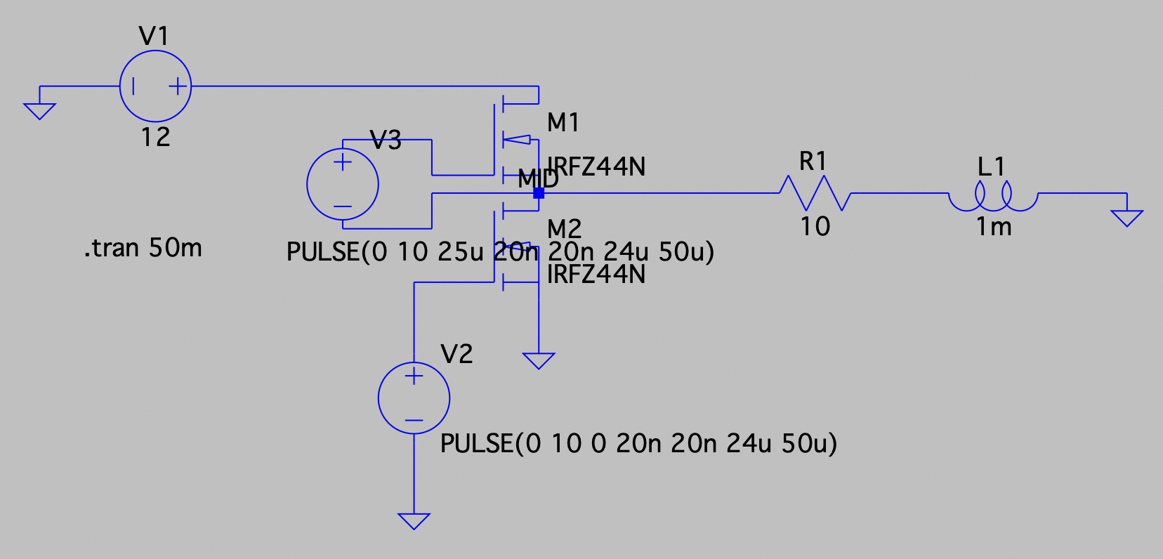
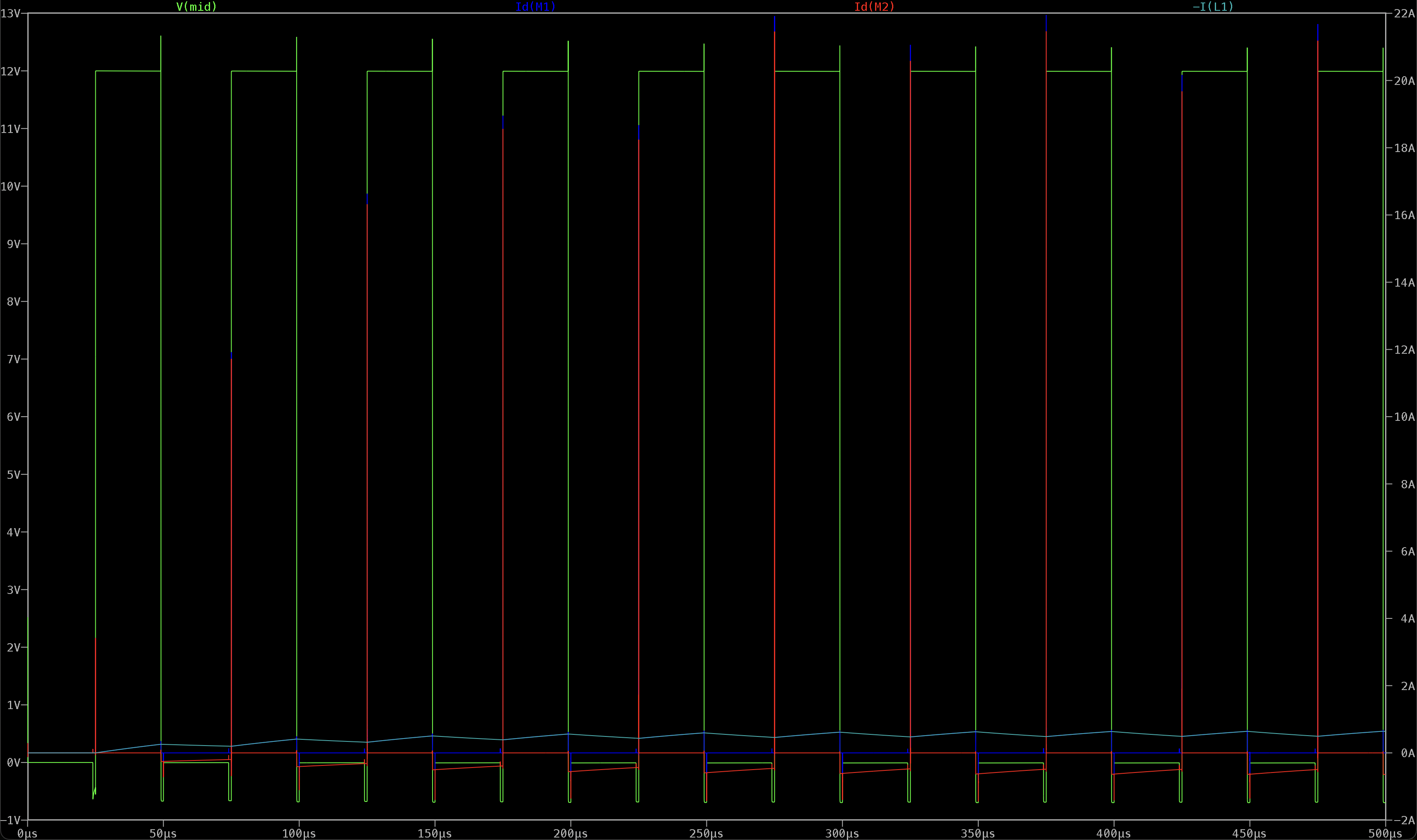
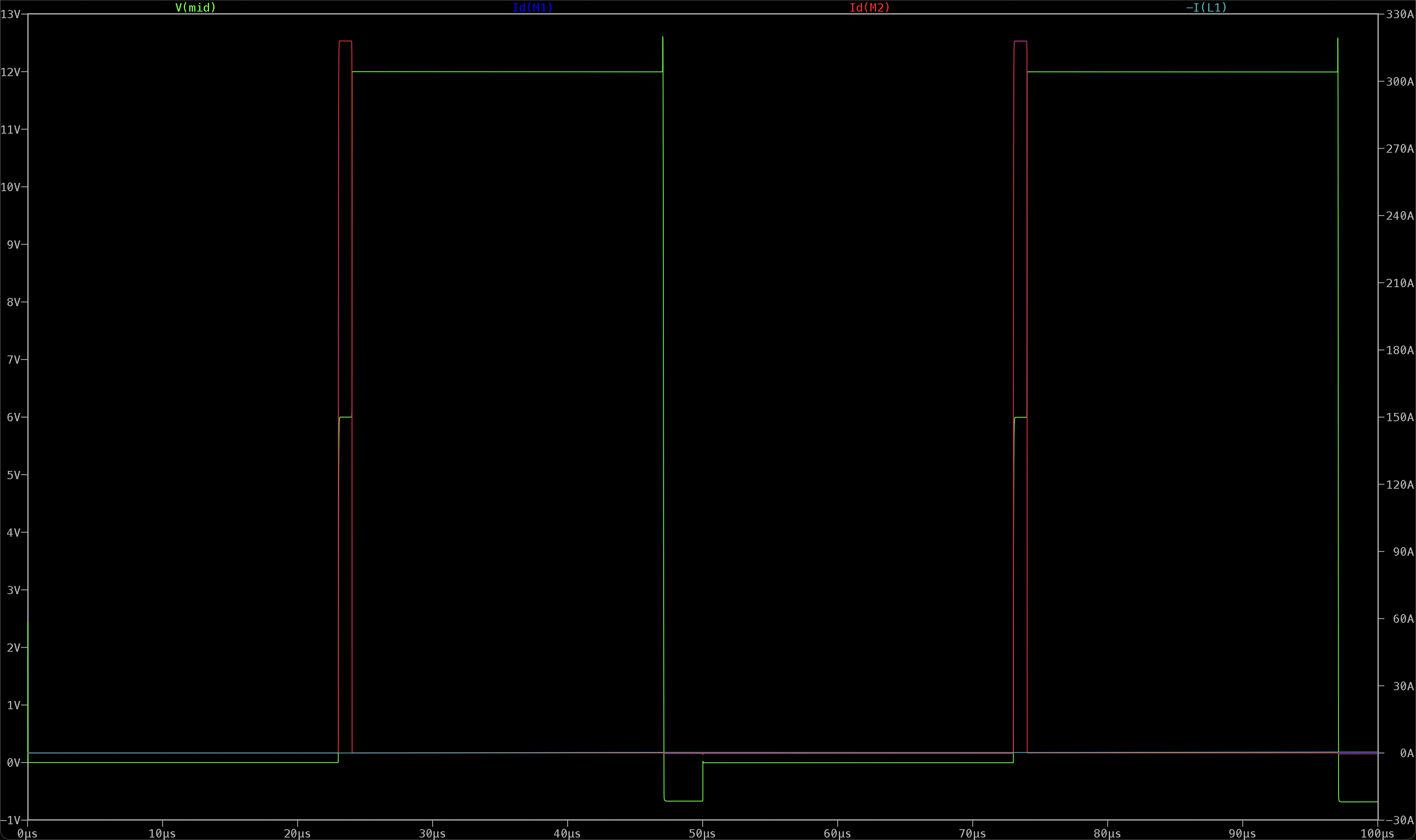
I simulated one half-bridge of the inverter in LTspice and built the circuit using two MOSFETs, PWM gate drives with 1µs dead time at a 20kHz frequency, and an RL circuit as a stand-in for the motor winding. I predicted the steady-state current by hand (by taking the duty-weighted average over winding resistance, yielding 0.576A), ran the simulation over five time constants, and measured a current of about 0.57A. Next, I deliberately overlapped the gate signals to demonstrate an example of shoot-through. I predicted a current of 343-430A from the FETs' on-resistance and measured a sustained current of about ~315A, with the switch node sitting at half rail, confirming that both FETs were on and the load current was unchanged, which is why the fault is so severe and why dead time is necessary. Among the additional experiments I performed was adding a 50nH parasitic inductance into the power loop to produce ringing at the switching node, and I also solved the FET's effective output capacitance (approximately 2.6nF) from the measured ring frequency.
- Jul 15, 2026First motor spin under field-oriented control on the ST development kit
- Jul 2026Completed system block diagram, concept sketch, and first-principles power stage design
| Part | Role |
|---|---|
| STM32G431 | Control |
| MPQ6531 gate driver | Gate drive |
| IPD090N03LG MOSFETs x6 | Power stage |
| AS5600 encoder | Position feedback |